Hydraulic Gear Pumps: How They Work, Benefits, and Common Applications
, by Surplus Warehouse, 6 min reading time
, by Surplus Warehouse, 6 min reading time
A complete guide to hydraulic gear-pump operation, common designs, applications, replacement selection, installation, and maintenance.
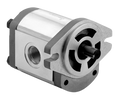
Hydraulic gear pumps are compact positive-displacement pumps that turn mechanical input into a steady supply of hydraulic oil. They are common in mobile equipment, shop machinery, agricultural systems, material-handling equipment, and many other applications because the basic design is durable, predictable, and easy to service.
This guide explains what happens inside a gear pump, why the design is so widely used, how the main pump styles differ, and what to check before choosing or installing one.
A hydraulic pump creates flow. Resistance to that flow creates pressure, so the pump must be matched to a system that can safely handle the intended operating pressure. In a gear pump, a drive shaft turns one gear while the gear teeth rotate a second gear. The rotating gears carry oil from the inlet side of the housing to the outlet side.
The main working parts are straightforward:
Each revolution moves a repeatable volume of oil. Actual output changes with pump displacement, shaft speed, fluid viscosity, internal wear, and system pressure. A worn pump may still turn normally while delivering less usable flow because more oil is leaking through enlarged internal clearances.
Gear pumps suit many working machines because they combine a small package with dependable performance. They also tend to tolerate the stop-and-start duty found in mobile and industrial equipment when they are installed correctly and supplied with clean oil.
An external gear pump uses two similar gears with teeth on their outer surfaces. This is the familiar design found on many tractors, log splitters, compact power units, dump equipment, and industrial machines. External gear pumps are valued for their straightforward construction and compact shape.
An internal gear pump uses a smaller external gear running inside a larger internally toothed gear. The arrangement can provide smooth operation and may be selected for systems where noise, inlet conditions, or fluid characteristics make it a better fit. It is not automatically interchangeable with an external gear pump.
Tandem and multiple-section pumps combine two or more pumping sections on a shared drive. They can supply separate circuits or different flow requirements from one input. Replacing one requires careful attention to section order, displacement, port orientation, drive capacity, and rotation.
Typical applications include agricultural implements, loaders, lift tables, dump trailers, power packs, conveyors, presses, material-handling equipment, machine tools, utility vehicles, and lubrication systems. The correct choice depends on more than the equipment name. Two machines that look alike can use different displacements, shaft rotations, ports, or mounting flanges.
Do not select a replacement from appearance alone. Record the information from the existing pump and the machine before ordering.
Cleanliness is one of the biggest factors in hydraulic-pump life. Keep ports capped until installation, clean nearby hoses and fittings, and do not introduce lint, sealant fragments, metal chips, or dirt into the circuit. Confirm that the reservoir contains the specified clean fluid and that filters and strainers are in serviceable condition.
Before startup, follow the equipment manufacturer's priming and bleeding procedure. Verify rotation before running the pump. Never operate a pump without oil, and do not use the pressure-relief valve as a routine flow control. After startup, watch for leaks, unusual noise, foaming oil, excessive heat, slow actuator movement, and unstable pressure.
Cavitation often sounds like gravel moving through the pump. Common causes include a restricted inlet, an undersized suction line, thick cold oil, a clogged breather or strainer, low reservoir level, or an air leak on the inlet side. Continuing to run a cavitating pump can quickly damage internal surfaces.
Use the identification plate and measurements from your equipment, then compare every specification on the product page. If a critical detail is missing, ask before ordering rather than assuming two similar-looking pumps are interchangeable.
Browse hydraulic gear pumps or use the site search to compare available configurations.